Call to order
817-488-2579
Acoustic Fluid Logger III
The Acoustic Fluid Logger AFL III is a traditional strip-chart recorder. The operator can shoot fluid levels on oil and gas wells, with no computer required. The Acoustic Fluid Logger III from Sage Oil Tools is a good option for situations where weather, location or personnel conditions make computer use difficult.
AFL III - How it works
The Acoustic Fluid Logger III identifies the distance to the liquid level in the casing annulus of a well by using the Pressure Pulse Gas Gun to send a compressed CO2 gas pulse down the annulus.
The compressed gas pulse travels down the wellbore until it reaches the fluid in the well; the compressed gas pulse then bounces back from the fluid and the echo returns to the surface.
A microphone inside the gas gun registers the returning echoes from the collars and the fluid, and delivers the signal to the logger via a microphone cable. The Acoustic Fluid Logger uses an analog-to-digital converter to gather all reflections from the collars and the fluid, and then plots them on a thermal paper tape strip-chart. It registers the casing joints and collars as small bounces or echoes on the fluid level tape, and registering the fluid in the wellbore as the biggest kick on the tape.
Using compressed mode shortens the fluid tapes to up to one-eighth of their original size, and keeps the one-second timing marks. Compressed tapes are easier to handle in the field, while offering a condensed view of events inside the wellbore.

Amplications for the Fluid Level
Different gain settings are gathered by the AFL III each time the operator shoots a fluid level. This allows the operator to print up to seven fluid level tapes with different amplifications of the fluid level signal without reshooting the gas gun. A multichannel filter in the Acoustic Fluid Logger III increases the signal amplification, which increases the AFL III’s ability to pinpoint the fluid level. When this signal amplification is combined with the compressed mode feature, which produces a shorter tape, it allows easy visual recognition of the fluid level.
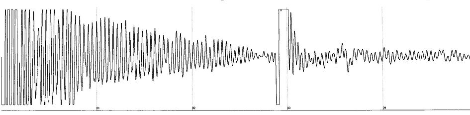
When shooting a fluid level, this square-root-of-amplitude plot is the initial tape presented by the Acoustic Fluid Logger III.
Default Plot:

Once the proper gain setting is determined for a well, you can specify that gain using the keypad, so that it will be the first tape printed.
Example Fluid Tapes: Gain Settings 1 through 6: Reprinting the same fluid shot at various gain settings.
Gain Setting 1: 1 Print

Gain Setting 3: 3 Print

Gain Setting 5: 5 Print
Calculating the Depth to Fluid
Counting the tubing collars between the shot and the fluid level kick with the aid of eleven-point dividers determines the distance to the fluid. Starting from the point where the fluid level shot is taken, the dividers are expanded to the point where each tip of the divider roughly meets a peak (representing a well collar) on the echo trace. The collars can then be marked and counted quickly by tens, and then counted individually to the exact fluid level. Multiplying the collar count by the known joint length in the well determines the distance to the fluid. So, in this example, 65 joints to fluid, multiplied by the joint length of 30 feet per joint, equals 1950 feet to fluid.

